Looking For Solutions?
Call Us Now
(503) 746-5807

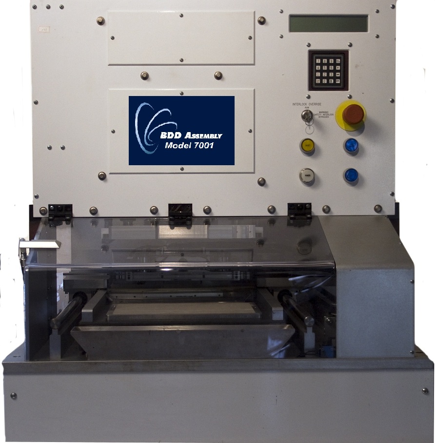
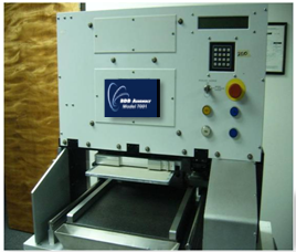
7001 Dipping Process
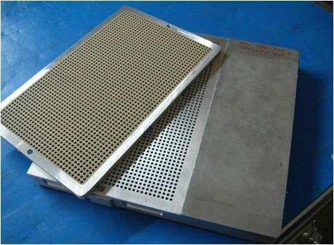
MODEL 7001 Dipping Process![]()
History:
The following termination process is very labor intensive. It requires 2 to more operators, a pin press assembly (246 Press with Press Conversion assembly), a dipping machine (2001 System) and a Conveyor Oven. This process requires the press assembly to load and transfer chips in the Carrier Plate for the termination
Present Day Process includes:
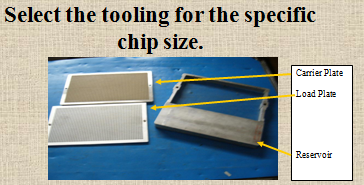
LOADING:
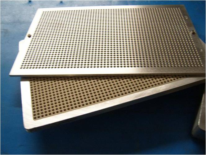
1) Place the correct size Load Plate on top of the Carrier Plate
2) Place chips into the Chip Reservoir tool. Reservoir is shown opening up.
3) Place the load plate and carrier plate onto the Chip Reservoir opening

4) Place this assembly, turning it over, onto the Vibration unit or manually shake it.
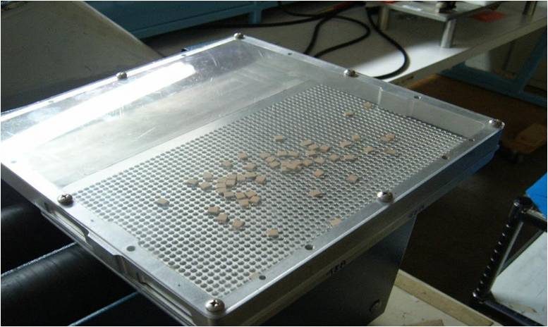
5) Vibrate the chips into the Load Plate. Chips will move from the pocket of the reservoir to the load plate area and fall into the open load plate holes.
6) Tilt the Chip Reservoir backward when the Load Plate is full. Make sure you do-not tilt it too far or the chips will unload from the load plate.
7) The excess chips will drop into the chip Reservoir pocket.
8) Place the complete assembly onto the table and remove the Chip Reservoir keeping the extra chips in the pockets.
PRESS CHIPS INTO CARRIER PLATE:
9) Pick up the Load plate and place it onto the 246 press with the load plate on top, loaded with chips.
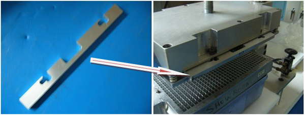
10) Place the correct spacer bars onto the press. Place a Spacer Bar front and back it needed between the upper pin late and the stripper plate. See the manual instructions if needed…
11) Press the operating knobs to activate the press and press the chips through the Load Plate and into the Carrier Plate
(Both knobs must be pressed at the same time to operate the press. If you remove pressure from any knob the press will open.)
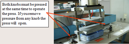
12) When you remove your hands from the knobs the press will open.
13) Carefully remove the Load Plate and Carrier Plate from the press
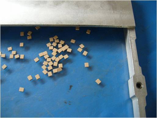
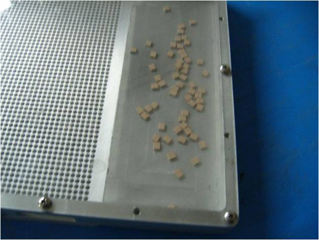
REMOVE THE LOAD PLATE:
14) Carefully remove the Load Plate from the Carrier Plate. Chips may be sticking up from the Carrier Plate into the Load Plate holes. Caution do-not bump the chips.
TERMINATE THE CHIPS:
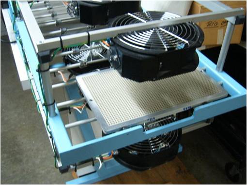
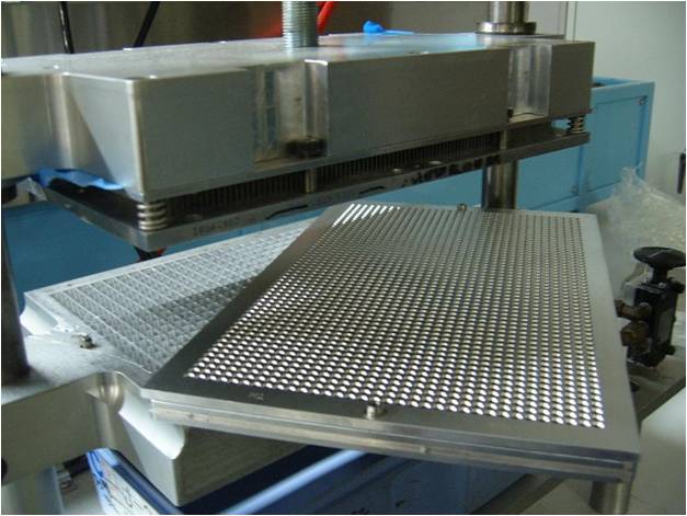
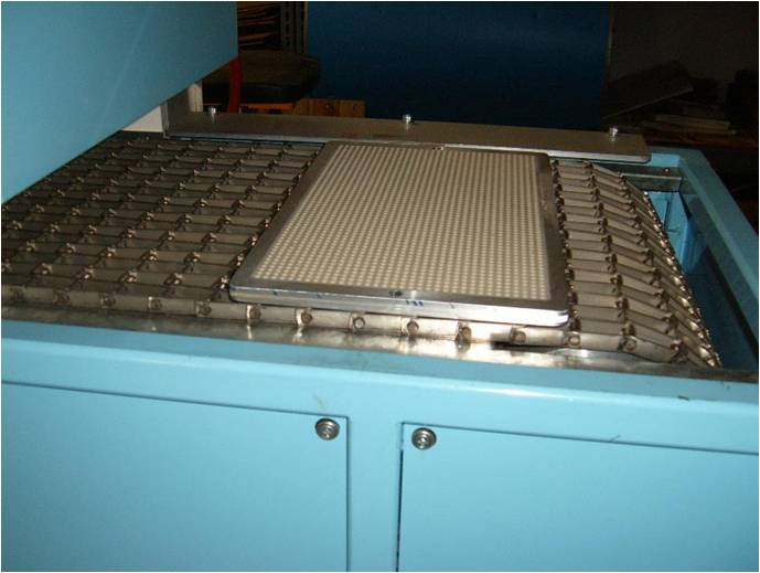
15) Place the Carrier Plate onto the 7001 ATM system, chips pointing down.
OPERATE THE 7001 SYSTEM:
16) The system will operate to the parameters that are programmed into the system. This operation applies the conductive paste onto the end of the chip on the end.
17) When the cycle of the 7001 is complete the door will open. Remove the Carrier Plate. Cautions the chips sticking out of the Carrier Plate have wet paste on them.

DRY THE TERMINATION PASTE ON SIDE ONE:
18) Turn the Carrier Plate over and place it onto the Oven Conveyor Belt to dry the termination paste.
19) When cooling is complete, the chips can be transferred for the second side termination or pressed out of the Carrier Plate if “one side only” termination is complete. If termination the second side restart at step 11 above.